The gimbal "Traveller Gimbal"
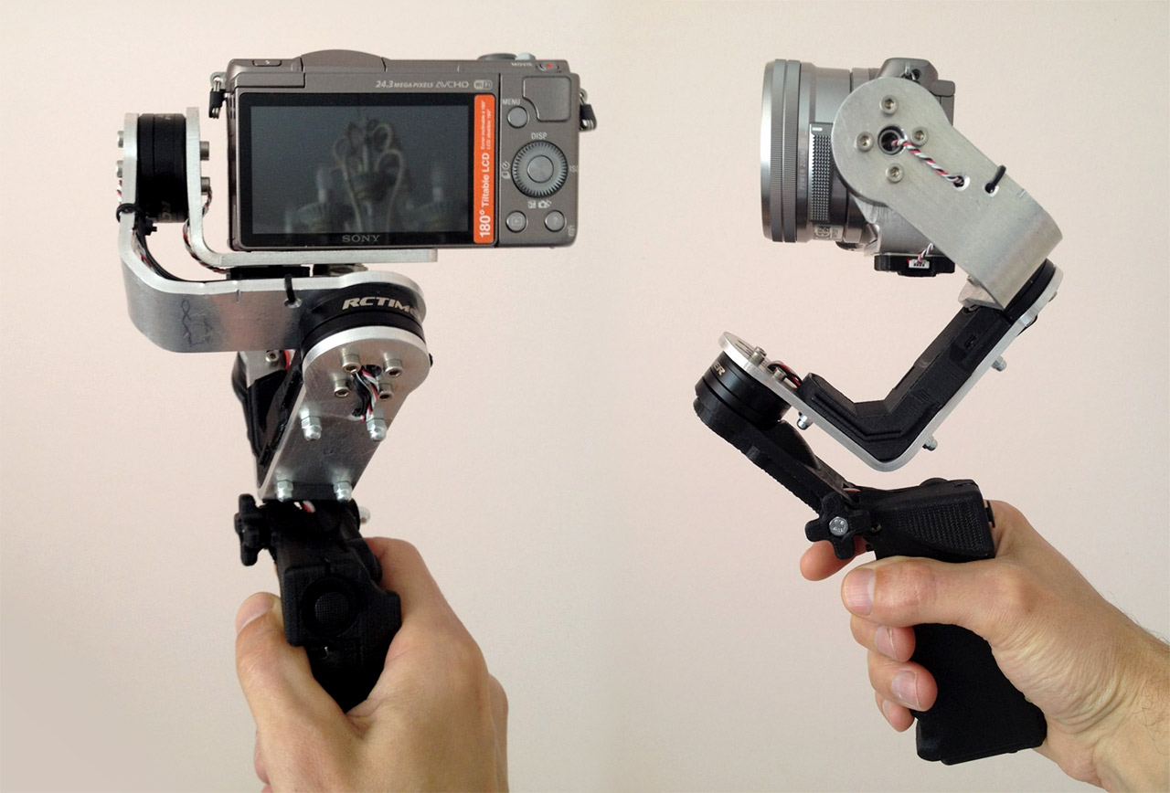
In this manual, we will show how to make the gimbal for Sony α5100 or similar cameras.
The main advantage of this gimbal is its small size and light weight. The handle of the gimbal is foldable. It allows you to carry the gimbal in a small bag or case. When folded it measures 21×12×5 cm. Two batteries 18650 are enough for several hours of operating.
You can check out capability of the gimbal in this video:
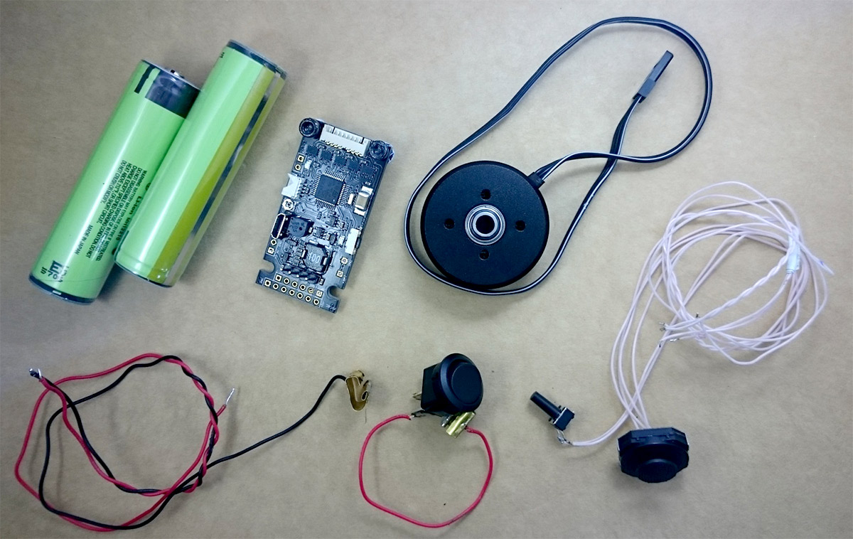
The following components will be used in the project:
- BaseCam Electronics SimpleBGC32 controller. The gimbal's body designed for the Tiny controller which measures 50×25mm;
- 3 motors Rctimer GBM2804 Hollow Shaft Brushless Gimbal Motor. Their power is enough for this gimbal. For bigger cameras you will need more powerful motors;
- PSP 1000 joystick;
- Rocker switch P-SM101-2B3, or similar;
- Two protected lithium battery 18650. Also, you can use unprotected lithium battery 18650;
- 11 mm long peg button;
- Machine screws with a flat top head M3×12 — 4 pcs;
- Machine screws with a flat top head M3×10 — 2 pcs;
- Machine screws with a button head for a socket drive M3×6 — 22 pcs;
- Machine screws with a button head for a socket drive M3×8 — 4 pcs;
- Hex bolt M5×45 and a nut with a nylon insert;
- Wood screws with a flat top head M3×15 — 1 pc and M3×20 — 3 pcs;
- Duralumin sheet 3–4 mm or aluminum 4–5 mm
- 3D printing and CNC machine to cut out aluminum gimbal's shoulders.
The Gimbal Design
Aluminum construction consists of 3 consoles: ROLL, PITCH, and YAW. It is necessary to cut them out of duralumin plate 3–4 mm thickness and bend. We used usual aluminum 4 mm. It is hard enough for our case. Mentioned sizes suit only for a camera Sony α5100 kit with a lens 16–50 mm. For different cameras and lenses, the console parts are different. You will need to find required sizes to get ideal balance relatively motors' axes. In the all three motors' mounts, we added the possibility of balance fine tuning.
General view of the ready parts:
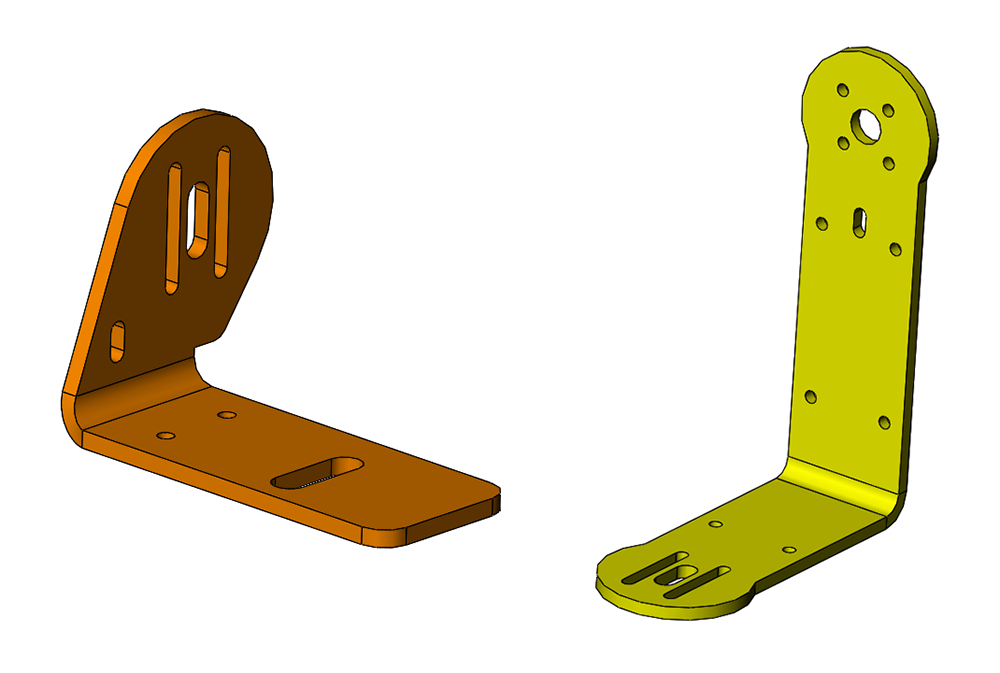 Pic. 2. Shoulders Pitch and Yaw should be bent at the 90-degree angle.
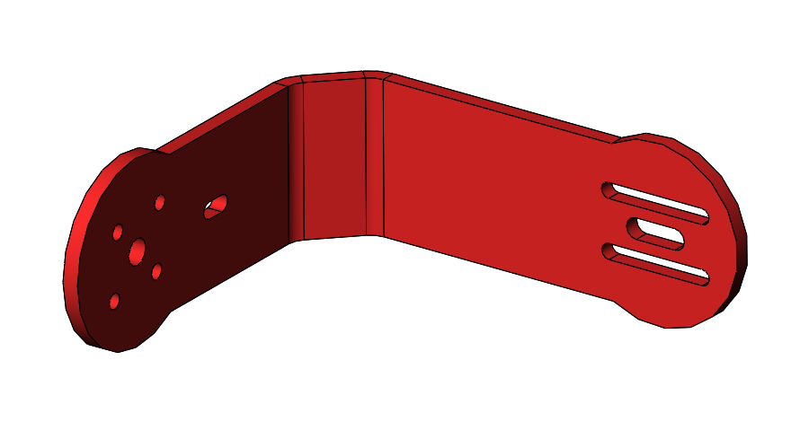 Pic. 3. Shoulder Roll should be bent at the 45-degree angle in 2 points.
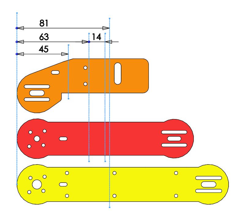 Pic. 4. Points of shoulders' bending.
It is necessary to mark holes with CNC machine to have possibility to attach parts precisely.
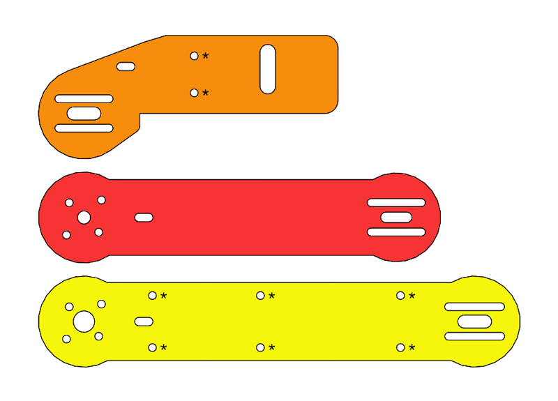 Pic. 5. Holes with screw-thread.
Mark 2 holes with CNC on PITCH part (Pic.5) and drill 2.5 mm holes and cut M3 threads for IMU attaching.
Mark 2 holes with CNC on YAW part (Pic.5) for Tiny controller attaching.
We advise you to bend parts with a special rig. If you don't have one, grasp parts tightly with a vise and bend them stepwise to avoid twisting parts.
Download the blueprints of aluminium parts.
3D Printed Parts
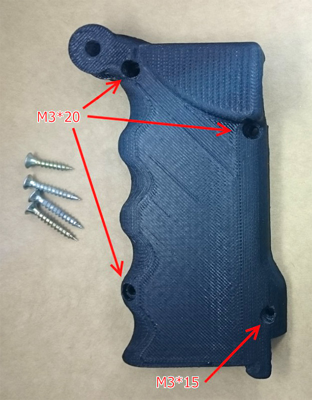
Handle consists of 2 parts (Pic.6). We advise to print them upper side up to get better quality of handle. Fill density should be not less than 50%.
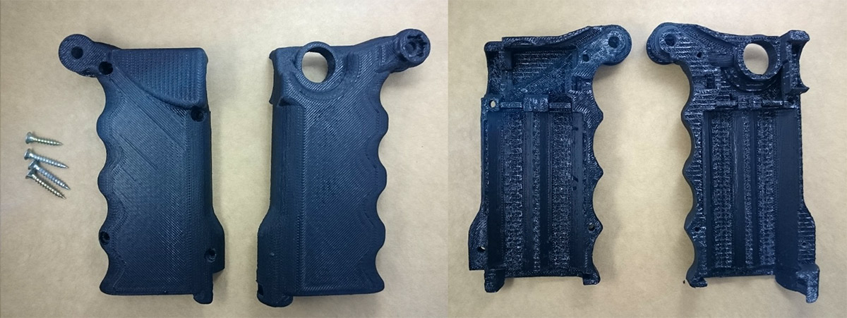 Pic. 6. General view of handle parts.
To attach handle parts, use wood screws M3×20 and M3×15.
Battery compartment (Pic.8) has the lid with the spring-loaded snap. To attach the button use machine screw from motors set with a button head for a socket drive.
The lid should have fill density 35% to be strong enough, the spring-loaded snap—not less 50%, the button—not less 35%. Print on the inside.
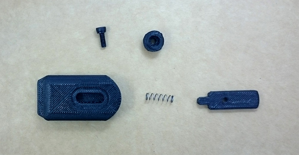 Pic. 8. The lid before assembling.
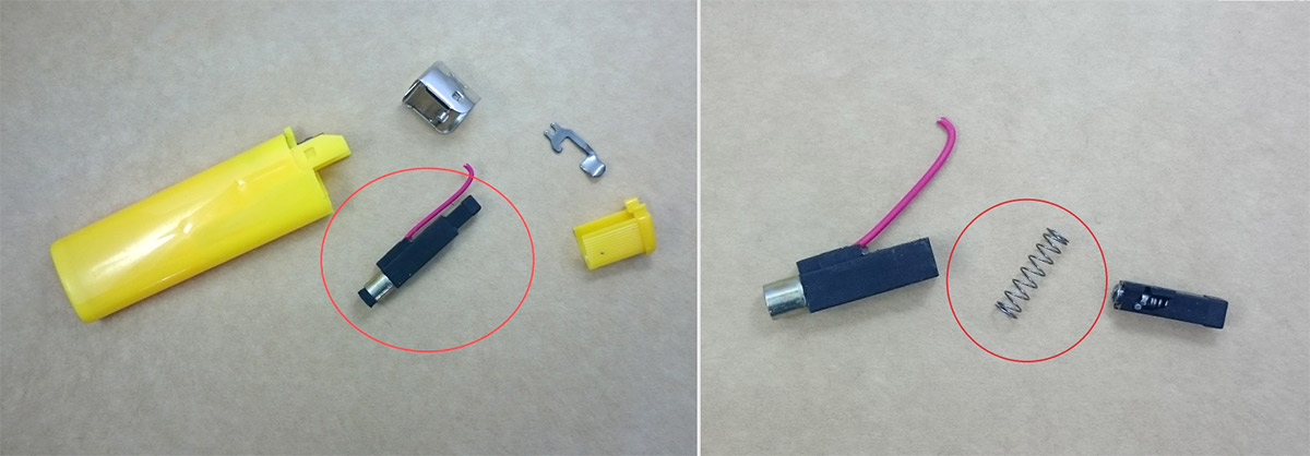
To remove supports from spring tube use drill bit 4,2 mm. Drilling depth is 37mm. You can take a spring from disposable lighter. There are 2 springs. You need softer one.
Moveable part of handle consists of the basic part and lid. (Pic.11) The lid is needed for wiring.
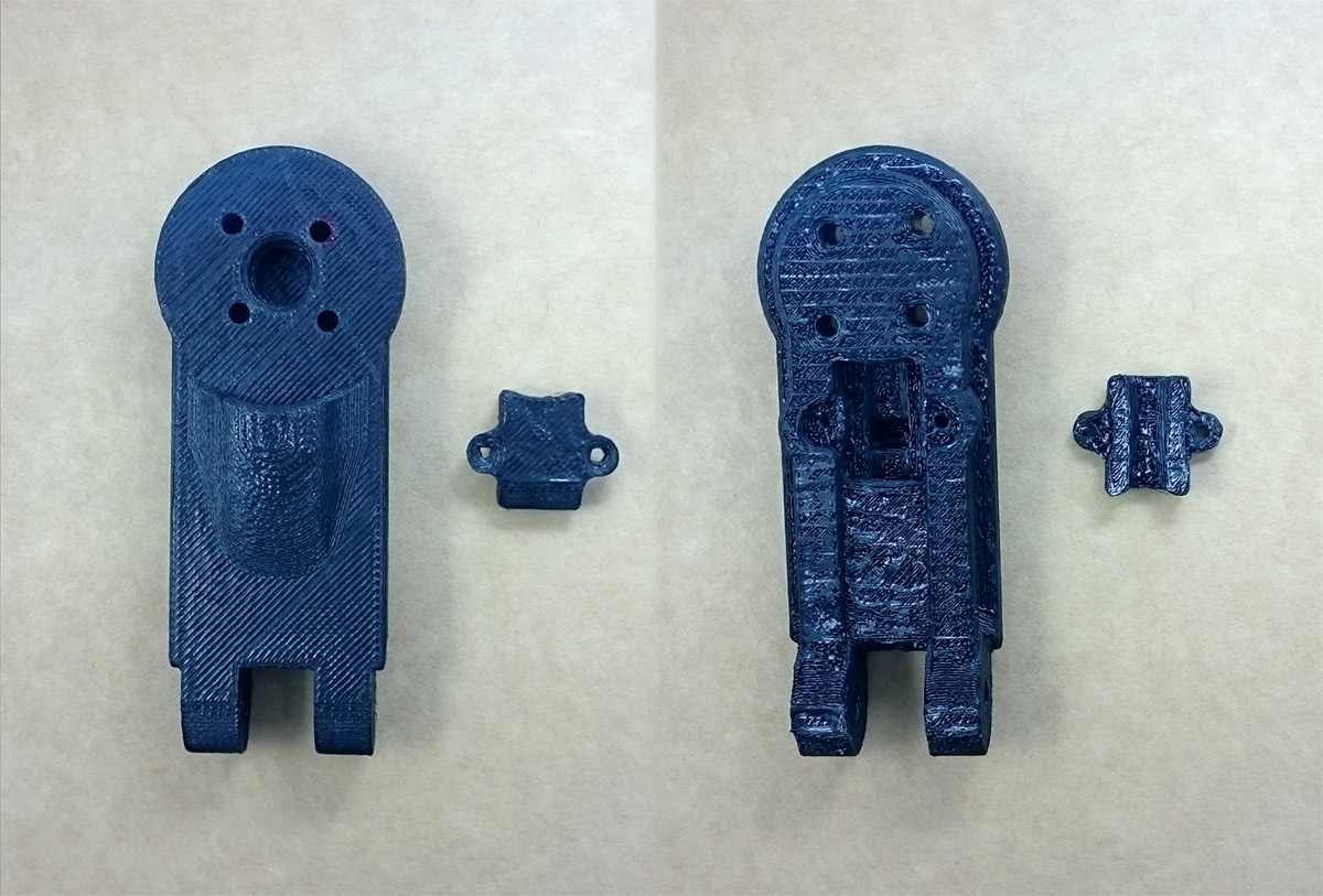 Pic. 11. General view of moveable part of handle.
The lid can be attached with two wood screws M3×15 or shorter. Besides, the lid holds good on 3D printed layers.
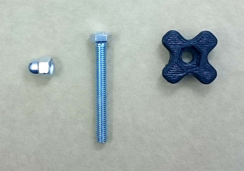
Attach both parts with hex bolt M5×45 and a nut M5 with a nylon insert. Thumb screw head also should be printed with 3D printer. Fill density is not less 60%.
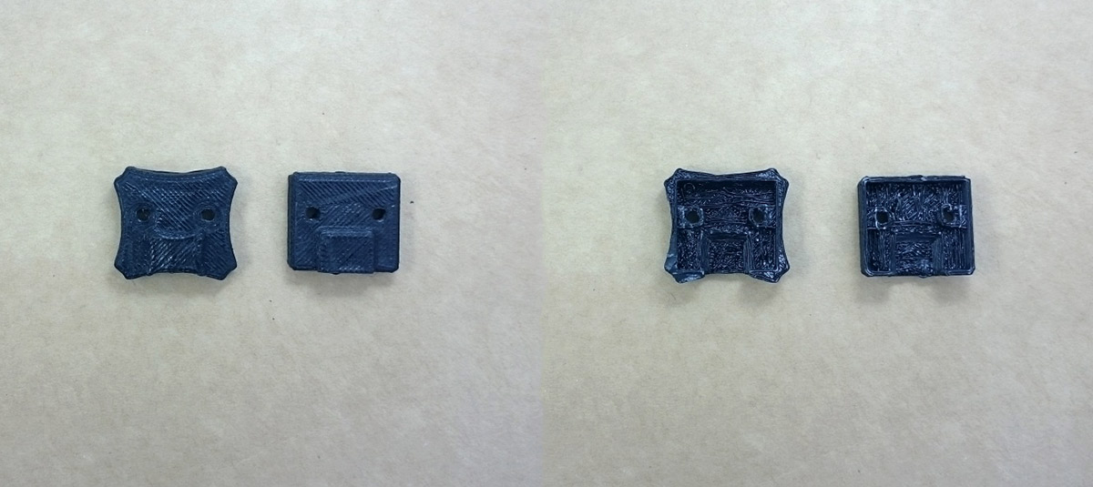
The mount for the Tiny controller consists of the mount part and lid (Pic.13). Also, the mount increases the rigidity of YAW shoulder. It is possible to connect USB cable to the controller when the lid is closed.
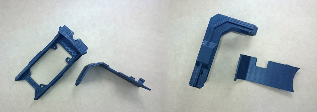 Pic. 13. General view of the mount for the Tiny controller.
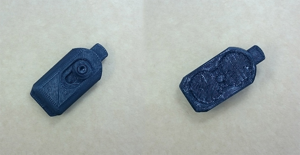
Besides, we advise to print the lid for IMU. There are 2 options.
Download STL models for printing.
The hardware
PSP joystick. Solder flexible and thin cables to the joystick.
Rocker switch. You need to solder one 20 cm cable and one short cable to the rocker switch. The long cable goes straight to the controller. The short cable should be connected to the switch.
It is required to bend contact pads for the battery 18650 from sheet brass or any other material which can be soldered. Besides, you can buy ready-to-use springs for that.
If you make contact pads yourself, we advise you to tin contact pads' parts which will be connected to the battery.
Here are the patterns with sizes:
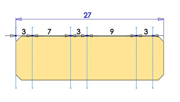 Pic. 16. The pattern of the contact pads for battery in the handle. Two contact pads are needed for plus and minus connectors. Recommended width is 8 mm.
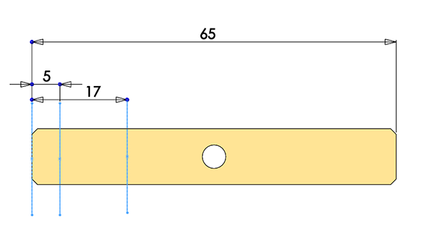 Pic. 17. The pattern of contact pads for battery in the lid. The size of the pad is intended to be used with protected 18650 batteries. You should just insert pad in the lid over the pin. The hole should be drilled with drill bit 4.2 mm. Recommended width of the pad is 10 mm.
Attaching the components and assembling
If you have prepared all the components correctly, everything will go smoothly.
Attach the motors with screws M3×6. The screws from the motor set don't suit because of too long. They can rest against the winding of motors.
Install components inside of the handle parts.
The batteries should be connected consecutively. Solder the long 20 cm cable to the minus contact pad. It will run to the controller. Solder the short cable from the switch to the plus contact pad. Run the long cable from the switch further, it will be connected to the controller. Check connections and mark the battery polarity. Install the joystick to the place and run 20 cm cables (see connection diagram).
Mount the handle's parts with the screws.
Carefully run the wires into the moveable part. Run the motors' wires. Attach the motor to the moveable part of the handle with machine screws with a flat top head M3×12. Close the lid. Screw up the screws, if you wish.
Assemble the lid. Fix the moveable part through the button with a bolt M3 from the motor set. Tighten it slightly that the locking part can move easily inside of the tray. Instert bent contact pad.
Attach handle parts with hex bolt M5*45 and a nut with a nylon insert (Pic.12) Check functionality. Fix the handle in folded state when assembling. This will help to get required wires' length for folding and unfolding the handle.
Assemble top part of the gimbal using the motors and aluminium parts.
Screw up the motors to the aluminium parts with screws M3×6.
Close IMU with the lid and screw up.
Note! Back side of the IMU has the bare contact pads. You should isolate them with insulating tape or plastic because their accident contact with aluminium parts of the gimbal can damage both the IMU and controller.
Run the wires, install the Tiny controller with motors output upward. aluminium surface should be isolated to avoid accident touching.
Carefully solder and connect electronic components with the controller.
Before soldering it is very important to check power supplying from batteries, have installed them in the place.
Note! Short circuit of lithium-ion batteries is very dangerous. It can cause battery ignition. Do not confuse the connection polarity. Wrong polarity can damage the controller and even your PC when it connected with USB.
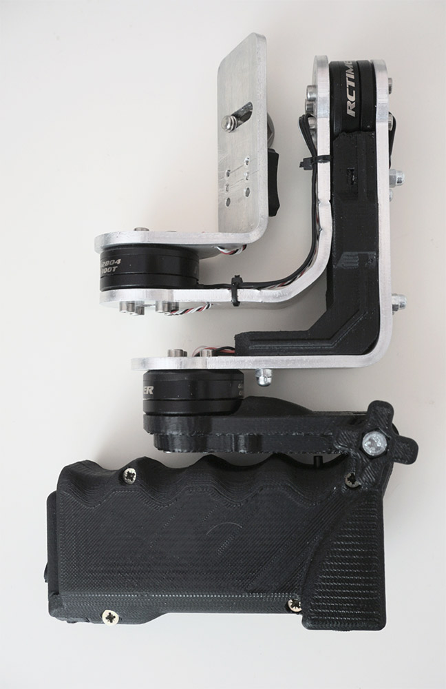
Attach both parts of the gimbal. Finally, we will have the compact gimbal with foldable handle.
Settings
The order of gimbal controller settings described in the User Manual. Before start to set it up make sure that the camera balance is good and there is no friction in the motors' axes. Since the motors have small power, the good balance is critical.
Setting advices:
- For these motors and power source, set POWER between 100–120 that not to overheat the motors. The voltage regulator on the Tiny board should be set for the maximum voltage — turned counter-clockwise up to the limit.
- It is mandatory to switch on Frame IMU which is on Tiny controller. During operating the Tiny controller can heat up to 60–70°C. It is recommended that you do temperature calibrating for Frame IMU.
- Set the battery low-level alarm for the 2 LiPo cells and enable motor shutdown on the low level to extend battery life.
- Enable voltage drop compensation since the voltage is not stabilised by the internal regulator for a 2-cell battery.
- Assign to the joystick on the outputs ADC1, ADC2 the control of YAW and PITCH axes.
- Different functions can be assigned to the button. For example, it can switch different profiles of camera control.
Example setting file for the 2.69b3 firmware.
Authors
Aleksey Moskalenko: the idea and setting
Andrey Talashenko: 3D-modelling, printing, assembling
Michael Shekhunov: CNC cutting

