How to Make an LCD-enabled Arduino Based Remote Controller for Gimbals with the SimpleBGC 32-bit Controller
30.08.2015
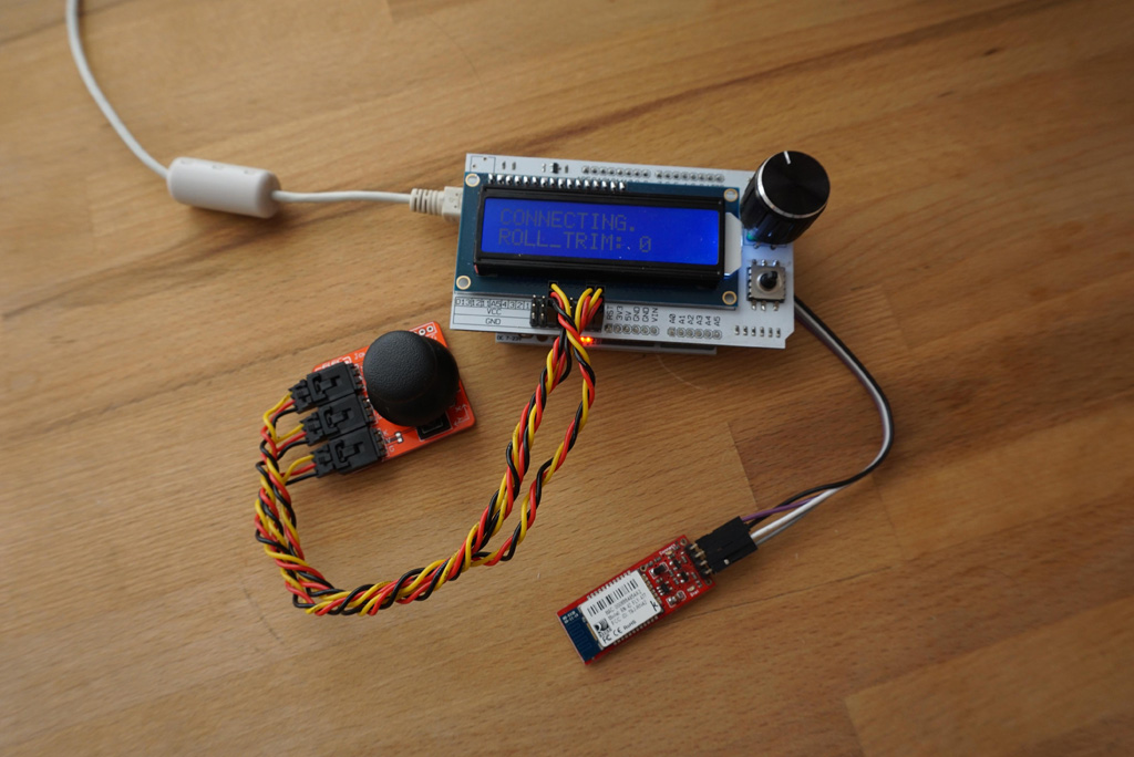 Remote controller assembled
This instruction will help you to build a simple remote controller with an LCD display for controlling a gimbal. The controller can be connected to any SimpleBGC 32 bit controller through the Serial interface. For that, you can use four-core cable, or wireless UART adapter (Bluetooth, 3DR modem, Zigbee, WiFi-UART, and so on).
- Displays the system statuses on multiple pages (use Up/Down arrows to scroll):
- battery voltage
- P: active profile
- E: average error of stabilization in 0.001 degrees
- communication errors, I2C errors, various debug information
- Controls PITCH and YAW axes of a gimbal with an analog joystick (passed to SBGC controller as regular RC channels). The joystick's push-button acts as the "Menu" button.
- Controls the tilt of ROLL axis with 0.1 degree precision (ROLL_TRIM)
- Displays a customizable set of adjustable variables (Left/Right arrow or encoder Push-button to scroll), changes their values by the rotary encoder.
- The navigation button "Select" turns motors ON/OFF
This video demonstrates capabilities of the remote controller
Required Hardware
You will need the following hardware:
- Arduino UNO
- LCD Key shield from elfreaks, that includes:
- 1602 LCD display
- Incremental Rotary encoder with push button
- 5-state navigation buttons (Left, Right, Up, Down, Select) connected to single analog input
- 2-axis analog joystick with push button.
- Wireless serial connection (optional): bluetooth in "master" role, in this example RN-42 is used.
- Brushless gimbal with the SimpleBGC32 controller.
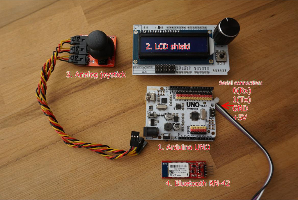 Hardware used in this example
Assembling and Connecting the Hardware
To connect the hardware together, refer to the section "Hardware configuration" in the LCDRemote.ino. If you use an LCD Key shield like shown on the picture, just stack it on Arduino.
Connect the joystick to shiled's outputs A1 (X axis), A2 (Y axis), D11 (button).
You have to solder serial cable manually due to RX, TX pins are not accessible when the LCD shield installed. The same can be required for GND and +5V.
NOTE: Since the Serial interface is used to upload the firmware, before uploading the firmware you have to unplug Rx, Tx from a Bluetooth module or SimpleBGC 32 controller.
Power can be supplied through USB cable, UART output of the controller (if a four-core cable is used), or from an external power source.
WARNING: DC converter of my Arduino UNO board produces a very big noise on ADC inputs. Take special actions to filter it out (for example, use 1nF capacitors). There is no such problem when powered from USB or external 5V source.
Connecting and Setting the SimpleBGC 32 Controller
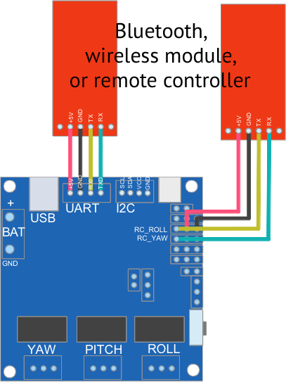 Options to connect with SimpleBGC 32 controller
The main UART output, or additional UART on RC_ROLL (Rx), RC_YAW (Tx) can be used for connecting. Note, that in case of using the main UART output, the simultaneous connection of the remote control and GUI is impossible.
To use additional UART select "RC_ROLL Pin mode" = "SBGC Serial API 2nd UART". With this option, simultaneous connection of the remote control and GUI is possible, that may be useful for debugging.
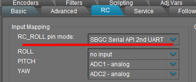
The SimpleBGC controller has to work on the 2.55b7 firmware or later.
The controller should be set in a normal way. If you did not configure RC control before, setup it as following.
PITCH, YAW: "SPEED MODE", ROLL: "ANGLE MODE"

MIN.ANGLE=0, MAX.ANGLE=0

SPEED=20

LPF=3

INITIAL ANGLE=0

DEADBAND=10

Expo curve=50
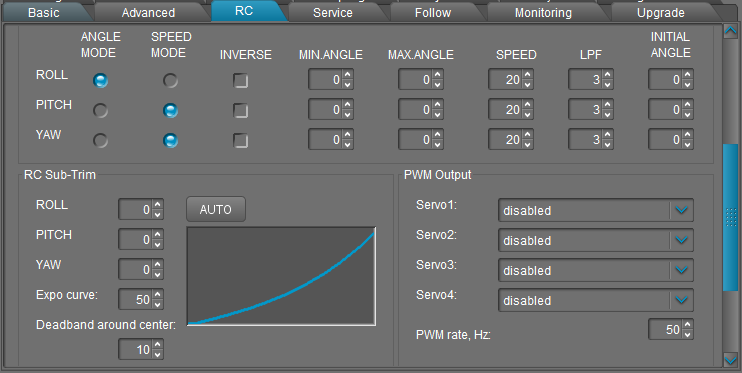
If you have already configured other source of RC control, no need to disable it: after the remote controller to be connected, it will be disabled automatically. All RC settings, excepting sub-trim, will be applied to the remote controller, too.
If you are going to switch profiles during work, do not forget to make the same settings in each profile.
In the "Service" tab, you can assign various actions to the joystick button (from 1 to 5 press in series).
Compilation and Uploading the Firmware
The latest version of the examples and libraries is published on GitHub.
Follow the instruction from Readme.md.
WARNING: It's recommended to increase the serial buffer size to the max. size of a command you want to receive. Default buffer is 64 bytes, that is not enough to fit incoming SBGC API commands. For this example, 150 bytes works well. You can set it in the file path-to-arduino-ide/hardware/arduino/cores/arduino/HardwareSerial.cpp:
#define SERIAL_BUFFER_SIZE 150
NOTE: enuine Arduino MCU has limited resources. Pay attention to the RAM consumption since in this example (for clarity and readability) there is no code optimization to reduce it. If you intend to continue evolving the software code, use basic approach to reduce memory consumption: define constants in the FLASH memory (use PROGMEM keyword), reduce a number of static variables, and monitor RAM space available (see "MemoryFree" library provided with this example).
Links
Video instruction provided by Dominik Bachinger: https://youtu.be/jNnRDc4Z_Ao
